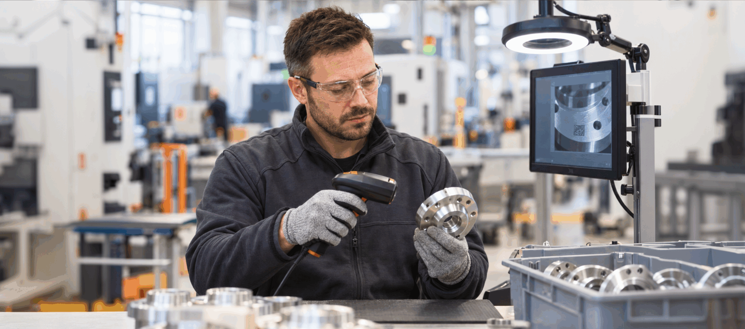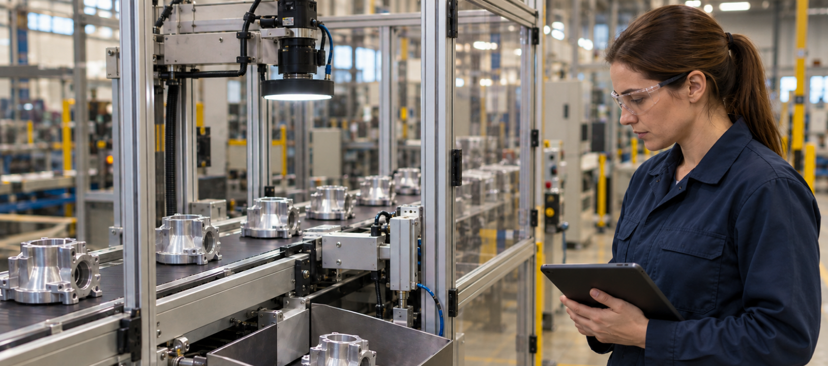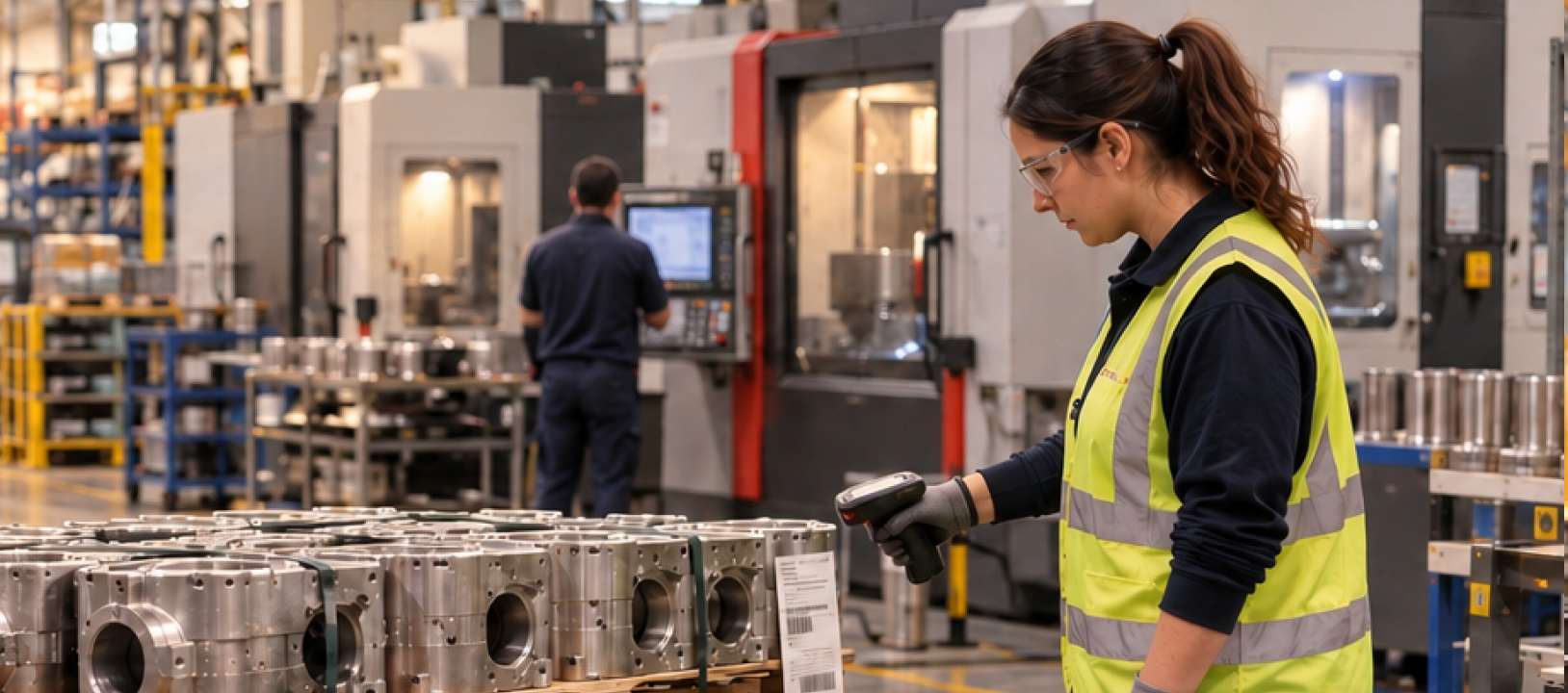







Automated visual inspection is easy to demo and hard to industrialize.
A model can classify a folder of clean test images in an afternoon. A production inspection station must handle changing lighting, surface variations, moving parts, new product families, operator overrides, line controls, and long-term maintenance.
That distinction matters because most project risks exist outside the model itself. Before purchasing hardware or collecting thousands of labeled images, determine whether the station can make repeatable decisions using the plant’s actual parts, at the required cycle time, and within the false-accept and false-reject limits established by the quality team.
Match the inspection method to the defect
Start with a defect register. For each defect class, define whether the system must detect its presence, classify the defect type, locate the affected area, or measure a dimension. These are different tasks with different imaging, data, and validation requirements.
Rule-based machine vision is often the best choice for stable geometry and clearly defined tolerances, such as a missing fastener, incorrect orientation, unreadable code, or edge in the wrong position. It is deterministic, fast, and relatively easy to audit.
Its weakness is brittleness. A change in surface finish, fixture position, or illumination can break a rule that worked perfectly during commissioning.
Supervised deep learning is better suited to defects that vary in appearance but can be represented through labeled examples, such as scratches, stains, porosity, or weld irregularities.
Anomaly detection can be useful when acceptable parts are common but defect samples are scarce. It learns a baseline of normal appearance and flags unusual cases for review. It does not eliminate the need for clear defect definitions, but it can support inspection while the defect library grows.
Not every defect belongs in a visible-light camera workflow. A NIST publication on casting-defect localization discusses X-ray imaging and other industrial inspection methods, including ultrasonic testing, magnetic-particle inspection, and computed tomography.
Visible-light computer vision should therefore be treated as one inspection method, not as a universal replacement for nondestructive evaluation.
Engineer the image before the model
The raw image sets the upper limit for system accuracy. If a defect is not consistently visible, additional model training will not rescue the project.
Work backward from the smallest defect the specification requires the system to detect. Determine the field of view, required pixels per feature, lens, working distance, and sensor resolution based on that requirement. Then test the setup using real parts from different suppliers, production batches, and shifts.
Lighting requires the same level of discipline.
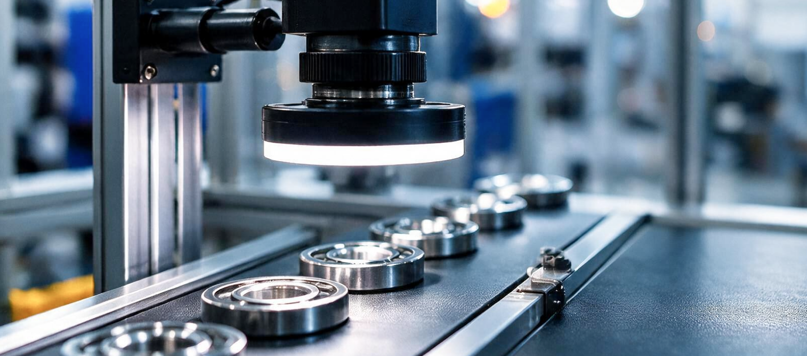
Diffuse or coaxial lighting can reduce glare on polished surfaces. Low-angle lighting can make scratches and raised edges more visible. Backlighting works well for outlines and dimensional measurements. Structured light or laser profiling may be necessary to inspect height, flatness, and shape.
The station should be enclosed when changes in ambient lighting could affect image consistency.
Fixturing is usually less expensive than teaching a model to recognize every possible part position. A stable nest, hard stops, and a reliable trigger reduce variation before the software receives an image.
Exposure and strobe timing must freeze motion. Image capture, inference, PLC communication, and reject actuation must all fit within the line’s cycle-time budget.
Before model development, confirm that:
- The smallest required defect is visible in raw images.
- Contrast remains consistent across normal part variations.
- Contrast remains consistent across normal part variations.
- Production speed does not introduce blur or missed triggers.
- Production speed does not introduce blur or missed triggers.
If the station fails any of these checks, stop and correct the imaging system before continuing.
Build the data strategy around production reality
Most factories do not have a clean archive of labeled defects captured under the optics planned for the new station. The project should account for this cold start instead of assuming that the required dataset already exists.
Begin with accepted parts from the actual production line. Include examples from different shifts, tool conditions, suppliers, and legitimate surface variations.
Use these images to validate the station and, when appropriate, establish an anomaly-detection baseline. As real defects and operator review decisions accumulate, label the highest-cost defect classes first and train targeted supervised models.
The defect taxonomy should be developed with experienced inspectors. Capture reference images and document the rules for borderline cases. Have more than one inspector label the same evaluation set, then resolve disagreements with quality leadership.
Inconsistent ground truth places a hard limit on model performance.
Synthetic defects and image augmentation can help address class imbalance, but they should remain training aids. Final acceptance testing must use genuine production parts that were excluded from model training.
There is no defensible universal number of images required for each defect class. Use learning curves and error analysis to determine when additional data is no longer producing meaningful improvements.
Design the station as part of the line
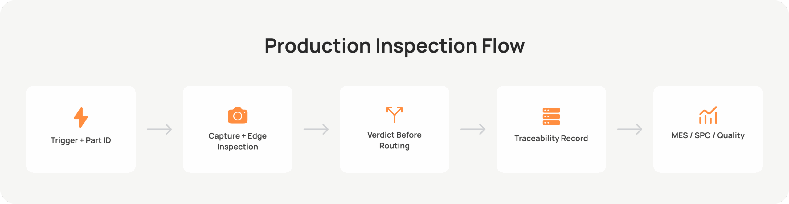
A production inspection system is more than a camera connected to an inference service. A practical workflow looks like this:
- A sensor or PLC triggers image capture and supplies the part or lot identifier.
- An edge device preprocesses the image and runs the inspection logic.
- The station returns a verdict before the part reaches the rejection or routing point.
- The result, model version, confidence score, calibration state, and selected images are stored for traceability.
- The required data is sent to the MES, SPC, or quality system for disposition and analysis.
AWS manufacturing guidance for automated visual inspection addresses many of the same operational concerns, including lighting variation, camera configuration, image buffering, production metadata, edge processing, control-system integration, and model monitoring.
AWS provides vendor documentation rather than an independent performance benchmark, but its engineering checklist is useful when planning a production system.
Brownfield constraints should be identified before the design is approved. Confirm the available cabinet space, PLC protocols, network boundaries, image-retention requirements, and whether the production line can continue operating safely when the inspection station is offline.
Define the system handshake, timeout, retry behavior, and fail-safe condition. “The model returned no result” must have an agreed operational meaning.
The model also needs a long-term maintenance plan. Track false rejects, confirmed escapes, confidence-score distributions, new product variants, camera changes, and calibration results.
Version the model and its dataset together. Test candidate versions in shadow mode, keep the previous approved version available for rollback, and assign clear responsibility for requalification after deployment.
Measure errors in business terms
Overall accuracy can hide the failure modes that matter most.
A system that accepts every part can appear highly accurate on a production line where defects are rare. Quality leaders need a smaller and more meaningful set of performance measures:
- Recall by defect type and severity
- False-accept rate based on an independently reviewed sample
- False-reject rate and the cost of unnecessary scrap or rework
- Tail latency, such as the slowest expected decisions rather than only the average
- Repeatability across repeated captures, shifts, and stations
- Throughput and downtime caused by the inspection cell
Set decision thresholds by defect class. A safety-critical flaw justifies a different false-reject budget than a cosmetic mark on a hidden surface.
Low-confidence cases should be sent to a fast human-review workflow that displays the source image, highlighted defect area, and relevant reference examples. Once reviewed and approved, those decisions can become labeled data for future model versions.
The economics of automated visual inspection should be based on the plant’s own performance baseline.
Before beginning the pilot, measure scrap, rework, sorting and containment labor, warranty exposure, inspection labor, and line stoppages.
The cost calculation should include:
- Cameras, lenses, and lighting
- Fixturing and mechanical integration
- Edge-computing equipment
- PLC and control-system work
- Data labeling and storage
- Calibration and maintenance
- Model retraining
- Technical support
Borrowed ROI percentages often hide more than they reveal. A defensible business case should be built using the plant’s actual costs and results.
Use a gated pilot, not an open-ended demo
Choose one production line and one costly defect class. Freeze a representative evaluation set before training begins and agree on the acceptance criteria with quality and operations.
The pilot should answer four questions:
- Is the defect consistently visible under real production conditions?
- Does the system meet the agreed false-accept and false-reject limits?
- Can it return a verdict within the line’s actual cycle-time budget?
- Can plant personnel calibrate, operate, and recover the station without relying on the development team?
Scale the system only after these answers have been documented.
The next gate should test MES or SPC write-back, model rollback, calibration procedures, and the onboarding of another part family. This prevents a polished demonstration from being mistaken for a maintainable production system.
A public Softarex real-time defect-detection case study demonstrates the scope of this work using bearing components.
The proof of concept combined high-resolution cameras, computer vision, an on-premises application, annotated data for traceability, and a dedicated robotic scanning station. Softarex reports processing more than 30 images per second and completing the inspection of one bearing ring in approximately three to five seconds.
Those results describe that specific system and should not be treated as a benchmark for other production lines. The transferable lesson is its architecture: imaging, inference, operator review, data storage, and production constraints were engineered together.
Scope the first station
Start with the defect, not the model.
Establish the current quality baseline, prove that the imaging setup makes the defect consistently visible, define the acceptable error and latency limits, and map the production-line integration before committing to a full rollout.
Softarex’s computer vision engineering team works across image acquisition, model development, edge deployment, and production integration.
If your organization is evaluating its first automated inspection station, request a feasibility review. Bring information about one production line, one defect register, representative sample images, and the required cycle time.
The goal should be a documented go-or-no-go decision, not another open-ended demonstration.