Computer Vision: Plane Automatic Landing

Computer Vision (CV) is a field of Computer Science that works on enabling computers to see, identify, process, and provide an accurate output. Just in the same way that human vision does. But, unlike humans, a properly refined Computer Vision system reduces the possibility of an output error to almost zero. And one of the possible uses of Computer Vision is a plane automatic landing system with algorithms for tracking normalization. Tracking normalization is an approach that allows parameter calculation of a picture’s geometric transformations in real-time.
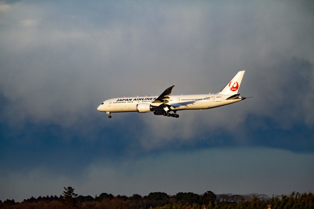
Landing a modern plane is quite a complicated and demanding process, which requires a special approach and the special attention of both the crew and ground services. To simplify it, an automatic landing system with Computer Vision can be of great help.
Setting the task of a plane’s automatic control during landing
Let’s consider the automatic control process of a plane during landing from a 400-500 m altitude. A plane moves along a rigid or flexible trajectory. In the first case, the trajectory of movement, the glide path, is set by ground devices based on radio equipment, and in the second — the plane’s position information comparatively to the landing point comes from onboard sensors.
The automatic radio approach system consists of onboard and ground equipment. The ground equipment consists of the glide path, course beacon, near, middle, and far marker beacons. Marker beacon transmitters are located in the direction of a runway’s centerline at distances of 60 m, 1600 m, and 7200 m, respectively. A plane begins to descend at an altitude of 300-400 m, i.e. the guidance line system begins to work after the plane passes the far marker. The advantage of this system is the autopilot connection and the disadvantage is the radio equipment complexity. They don’t perform well with narrow radio signals reflected from the ground when a plane is descending from low altitudes.
Aircraft tracking automatically controls a plane during landing by real-time video frames. Next, landing is controlled by the mathematical model of a plane’s movement. In this case, CV begins to control a plane after it passes the far marker — 7200 m.
Controlling a plane’s automatic landing with Computer Vision
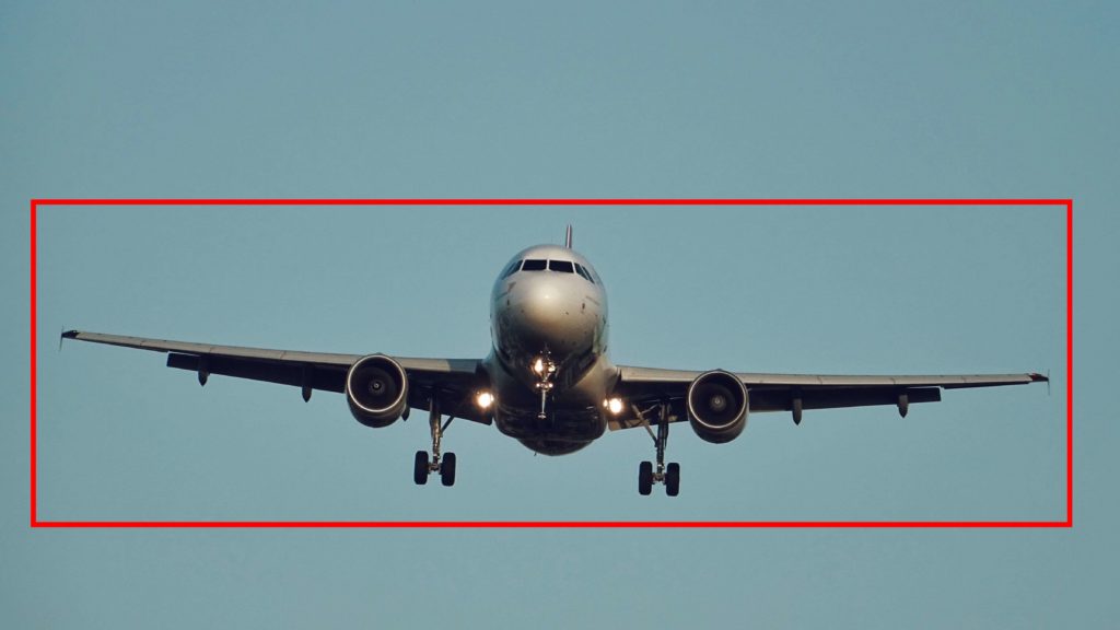
The system’s first stage is the plane’s capture at the time of its visibility zone entry. A dispatcher indicates it on a display screen, which displays the camera’s view field or automatically by using recognition and segmentation algorithms. The bounding box is placed on a plane’s image and the tracking process begins. The CV remembers the field of view before a plane enters the visibility zone, in order to exclude the background from the image during the tracking process. This increases the noise immunity of the system.
Next, the plane lands on a glide path. The glide path is set by a radio beam emerging from a glide-beacon located near the runway at a 2-3 ° angle. When a plane’s landing is controlled using CV, the video camera of the system must be set at the angle of inclination of the observation line Θ at 2-3 ° so the glide path line will be implemented and coincide with the line of sight. The CV camera is installed in the same place as the near marker beacon. A plane is at an altitude of 16-25 m. when it passes this beacon.
During a landing, an autopilot controls a plane so that the velocity vector of its center of mass is directed along the glide path. When a plane doesn’t move along the glide path its image, and accordingly the center of the bounding box, will be shifted relative to the center of CV view.
It is necessary to control the approach of both the plane’s image and the bounding box to the center of a field of view. The match of the center of a bounding box and the center of a field of view will be the stopping criterion of an onboard system control work. But CV will monitor a plane until it successfully passes the near marker — the place with installed CV.
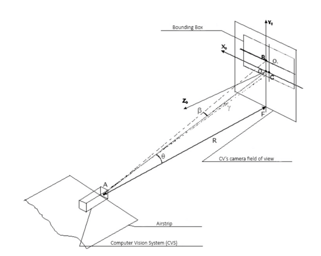
Figure 1 shows the time point t0 — the capture of a plane by an automatic landing system. The diagram shows that the center of the tracking frame is offset from the origin of coordinates in the X0 Y0 plane. Points В and С are the intersections of the coordinate system Xs and Ys, lying in the tracking frame, with the axes X0 and Y0. We connect them with the center of the image in a CV’s camera, through which the line of sight passes and we get the β angle — the course deviation from the line of sight in the vertical plane and the γ angle — the course deviation in the horizontal plane. The pixel distance from the center of the tracking frame to the Х0 axis is denoted by η, and to the Y0 axis — ζ. The deviations of the tracking frame from the center of the field of view can be determined since the coordinates of the center of the tracking frame are always known.
Mathematical model definition of a plane’s steering elements control
To solve the problem of guiding a plane to a glide path on the correct landing course, it is necessary to build a control law that will automatically eliminate the existing course deviations and accordingly reduce the deviation of a bounding box to zero. Thus a CV will control the process of approaching the aircraft to the glide path.
The deterministic mathematical model of a plane’s movement is based on the following parameters:
- Plane parameters — mass, speed, jet thrust, wing area, fuel consumption
- Environmental parameters — the speed of sound at a given height, air density, known as a function of height H at a constant temperature
- Motion parameters of a plane — angle of attack, a moment of inertia of a plane relative to the z-axis, angle of inclination of a trajectory, angle of deflection of an elevator, pitch angle
In the development of plane control equations, this model is fundamental at all flight stages.
For glide path landings, a simplified disturbed motion equation is used with small deviations of the direction of the velocity vector of the plane’s center of mass from the direction of the glide path. It is formed by linearizing the general model of the plane’s motion. The main parameters of the simplified equation are η — the magnitude of the mismatch of the current and the required plane’s altitude, and Δδ — the elevator angle deflection.
The output coordinate η should be measured in flight, as well as the value of the control function Δδ — the elevator deviation from the required angle. To create a control system, it is necessary to close the back control object, where η becomes the input function, and the output function. The function connected with the input coordinate is called the control law.
Using the control systems principles synthesis in conditions of uncertainty, we build an adaptive control system, which is reduced to the equation:
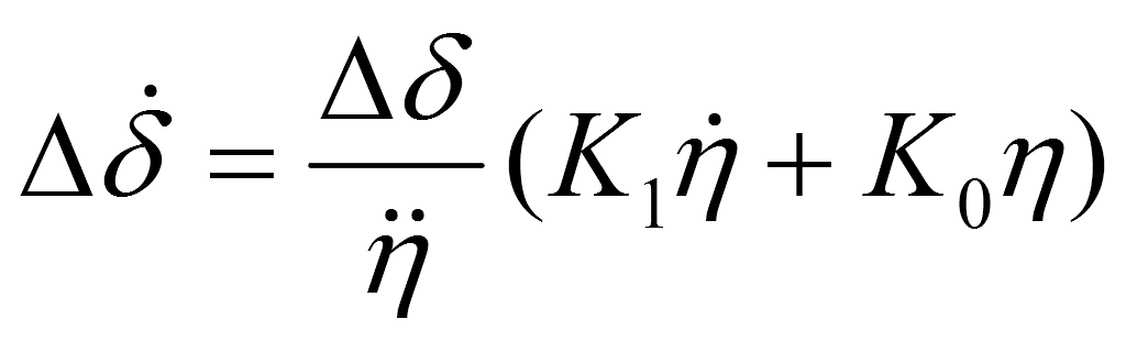
, where k — is a plane’s characteristics coefficient, whence inequality of the denominator follows. The coefficients К1 and К0 are formed by solving the system of Riccati equations.
Thus, the control law for the plane’s elevator is determined, which associates the value of the elevator deflection angle δ with the deviation of the plane’s flight altitude η from the required one. Using this control law, it is possible to determine the value of the deflection elevator angle at any time.
To determine the η initial value mismatch — η k pixel value is used. It is defined in the field of CV’s view, as the distance from the center of the tracking frame to the Х-axis. These values are interconnected through a scale factor. The magnitude of the scale factor is set based on CV’s lenses the parameters. The coefficient for substitution in the equation is reduced, the first and the second derivative η k values are calculated as the projections of speed and acceleration on the Y0 -axis:
Rewriting the equation №1:
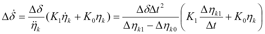
Where Δηk0 — is the deviation change of the bounding box center at the previous step of the Х0 -axis at the t0 moment of time, Δηk1 — the center deviation change of the tracking frame from the Х0 -axis at the current step at t1 time, ηk — the center deviation of the tracking frame from the Х0 -axis.
The coordinate system Х0Y0 is located in the center of the CV’s field of view. The ηk value, in this case, is the distance between the center of the tracking frame and the X-axis.
The equation shows the connection between the parameters obtained by normalizing the bounding box and the deflection angle of the plane’s elevator. It does not contain the distance to a plane or the height of its flight. This eliminates the need for additional sensors in the automatic landing system and significantly reduces calculation errors.
The Δδ value is measured by a plane’s onboard sensor and transmitted to the autopilot. The automated landing system transmits the bounding box deviation to it from the center of the field of view. The autopilot calculates the required elevation angle change of the elevator at the current step. Similarly, we can obtain the control equation for the rudder angle.
The equation №1 can be converted to a discrete form based on finite difference operators, which will allow calculations on a computer.
In this case, the magnitude of the ηk mismatch is also measured via CV as before. The derivatives are replaced by finite difference operators.
Conclusion
The described approach can be used as additional assistance for pilots during the landing process and provide information from outside observation. At the same time, the approach is quite theoretical and requires more research, modeling, and computer simulation with a real landing process video.
Want to know more about how AI and Computer Vision digitize the aviation industry? Check out our article about the future possibilities this technology might bring. We are always eager to share our best practices and open to learning something new, so if you have any questions or ideas — feel free to write to us. Let’s transform the world together!